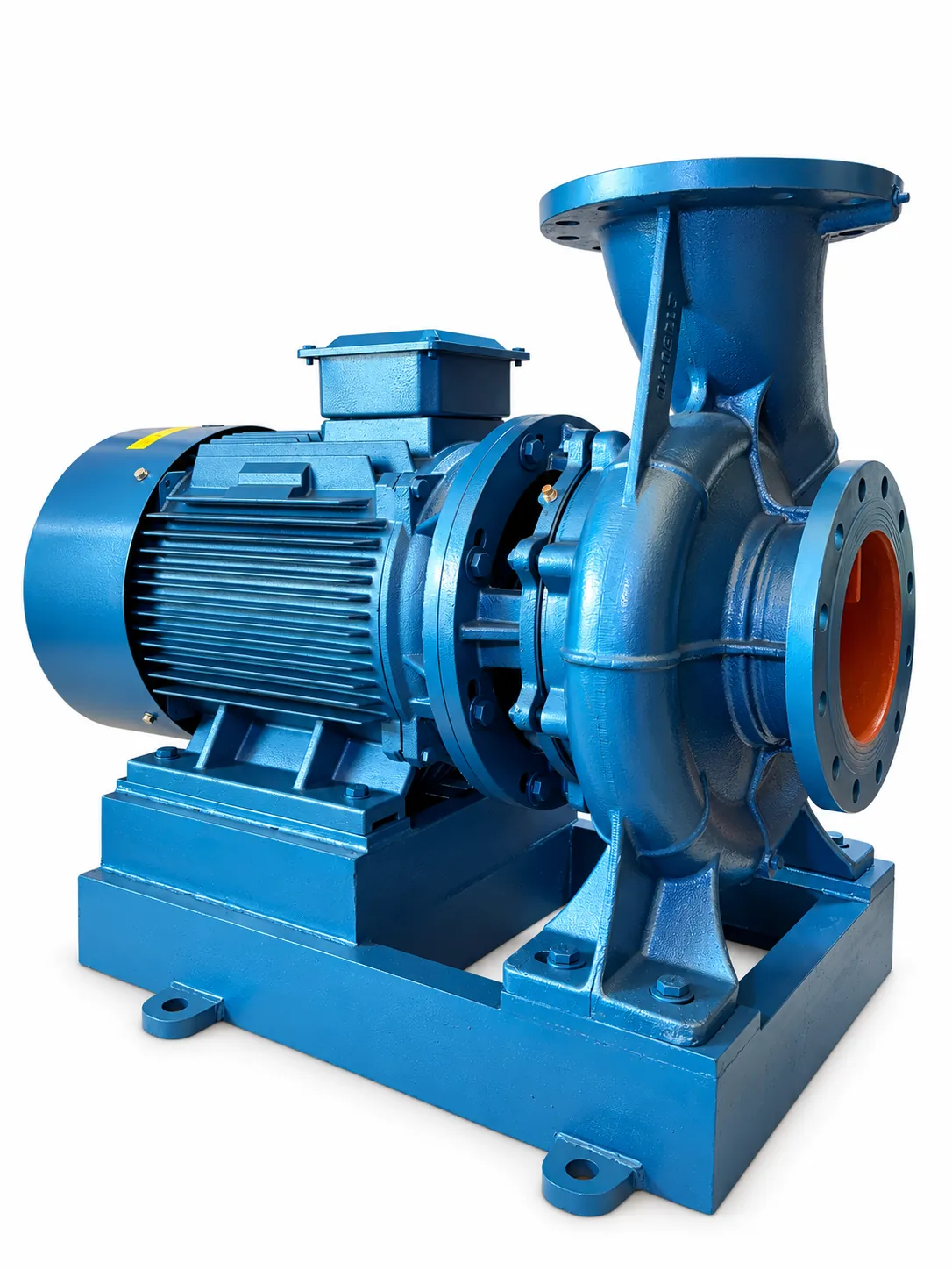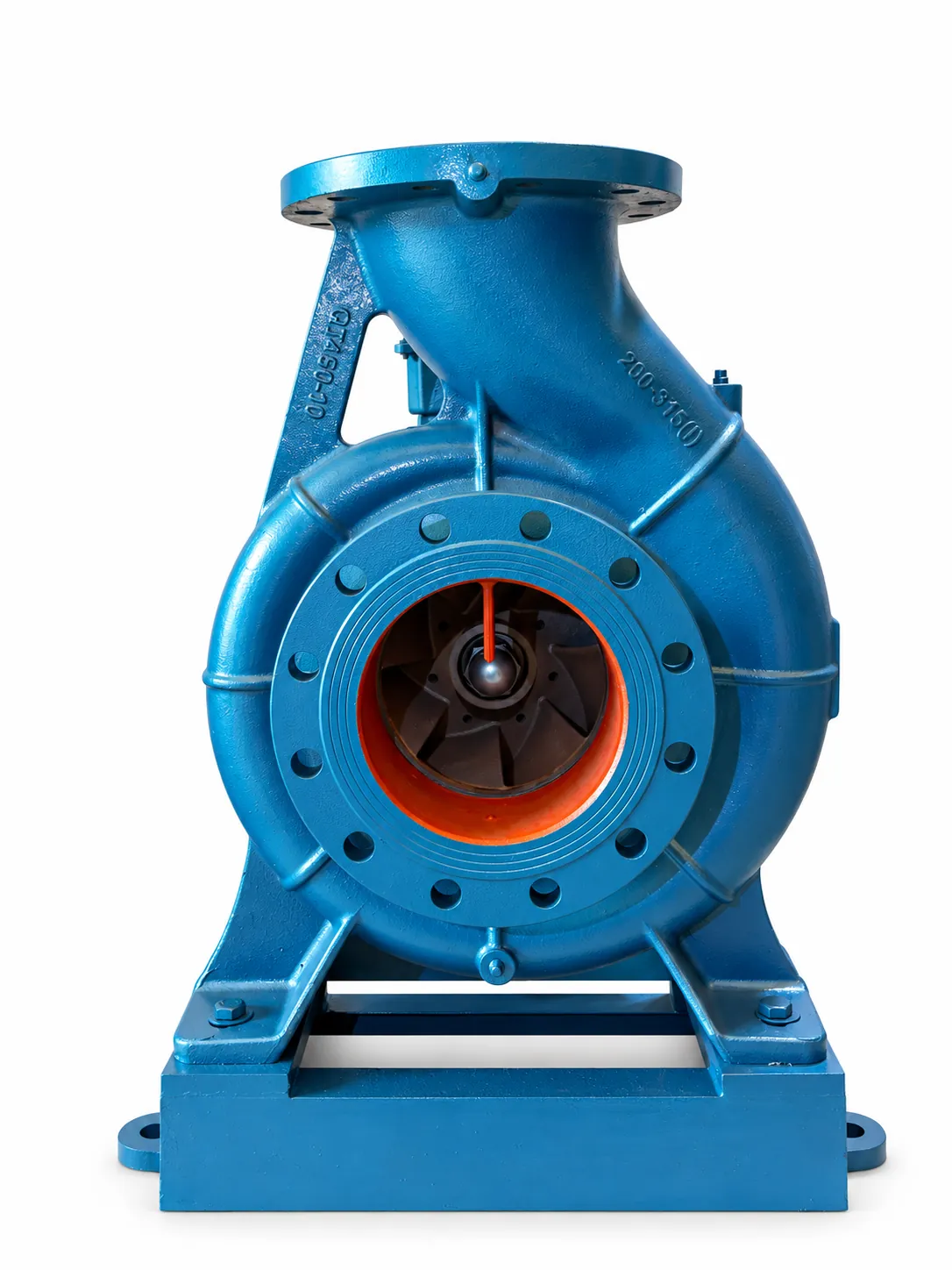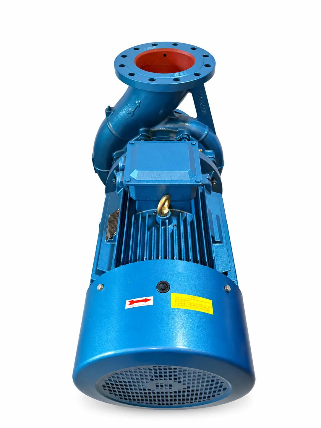
Compare the complete installation arrangement
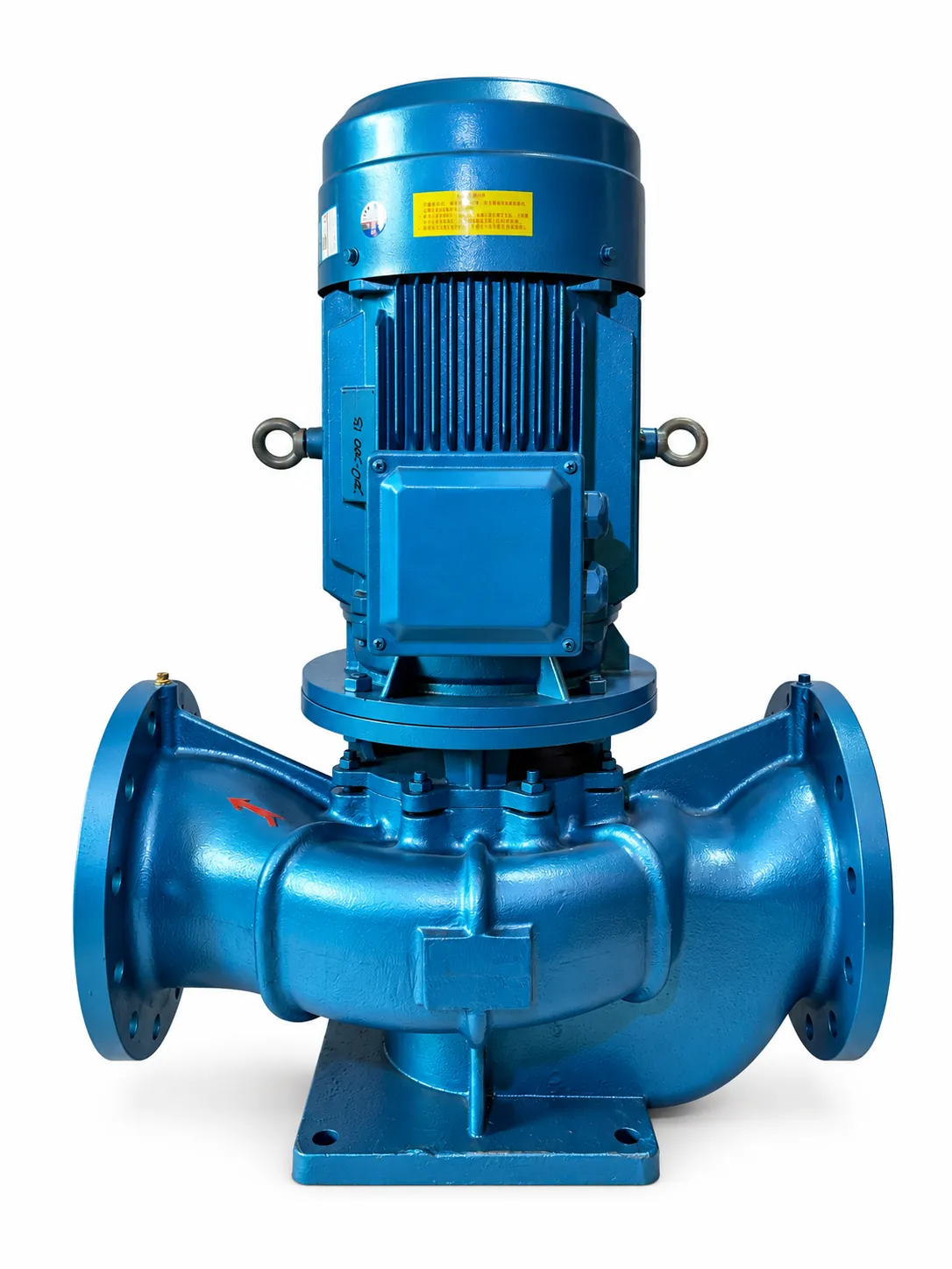
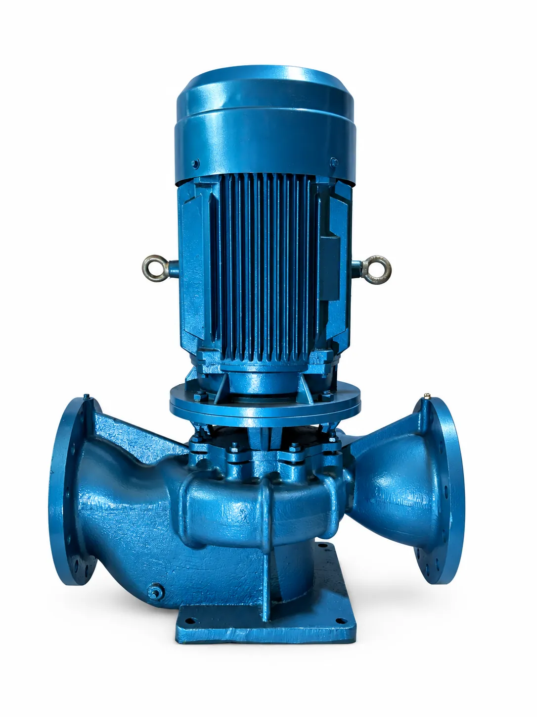
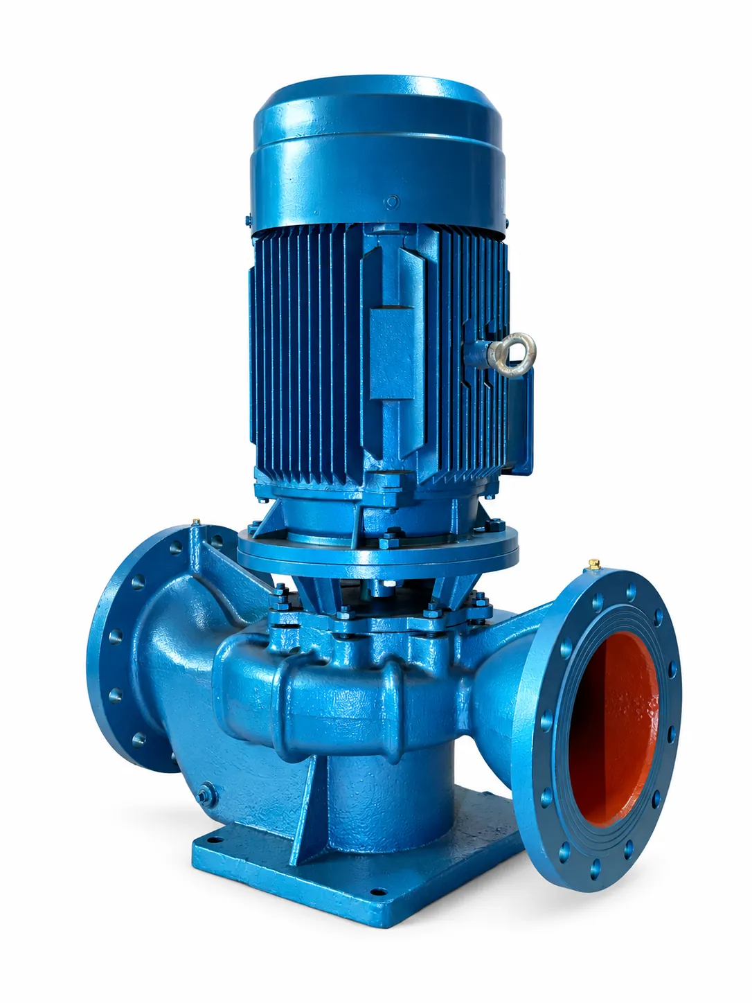
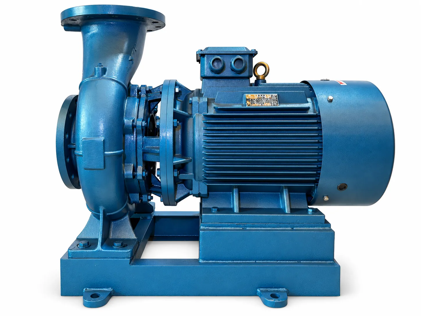
The FOBENG ISG product is a vertical centrifugal configuration, while the ISW product has a horizontal motor arrangement. This visible difference is a useful starting point, but the selection also depends on the actual inlet and discharge positions, operating point, liquid, dimensions and installation requirements.
The supplied ISG photograph shows opposite side flanges beneath a vertical motor. The supplied ISW photograph shows an axial inlet, upward discharge and horizontal motor on a base. Check the proposed model drawing before assuming that the ports are arranged in the same line or that one unit will replace the other without piping changes.
This guide turns those differences into a practical procurement and layout review. It does not rank one orientation as universally better. A suitable configuration is one that matches the duty and can be installed, supported and maintained within the project requirements. The quoted model data remains the basis for the final choice.
On this page
- Compare the complete installation arrangement
- What to check on the series pages
- Vertical and horizontal arrangements affect layout
- Use the same flow and head for both proposals
- Confirm the liquid, temperature and materials
- Review the inlet and piping arrangement
- Confirm power supply and control scope
- Two situations that change the decision
- A checklist before choosing the configuration
- Turn the information into a selection discussion
- Turn a replacement photograph into a reviewable brief
What to check on the series pages
Use the ISG vertical pump page and ISW horizontal pump page to identify the series and view the supplied product photography. The images help establish the overall construction and the visible port arrangement.
For an actual project, request the dimensional drawing and curve for the proposed model. Confirm that the identification, motor arrangement and connections in those documents correspond to the item being quoted. A general series photograph may illustrate the construction without defining every dimension of every model.
For replacement work, compare the proposed drawing with the existing installation rather than relying only on a familiar series designation. Include fixed pipe interfaces, foundation constraints and the clearance available around the motor. This helps the discussion move from a name match to an installation match.
Vertical and horizontal arrangements affect layout
| Installation question | ISG route | ISW route |
|---|---|---|
| Overall arrangement | Vertical motor above the pump body. | Horizontal motor beside the pump body on a base. |
| Visible connection pattern | Supplied photograph shows opposite side flanges. | Supplied photograph shows axial inlet and upward discharge. |
| Space review | Check total height, lifting and overhead access. | Check length, base footprint and access around the motor. |
| Mechanical confirmation | Use the proposed model drawing and mounting requirements. | Use the proposed model drawing and mounting requirements. |
A vertical arrangement can change how space is used, while a horizontal arrangement changes the footprint and service access. These are layout considerations to evaluate against the actual equipment. They do not establish the hydraulic performance, efficiency or suitability of a particular model.
Discuss the space needed for future service as well as the space needed to position the new equipment. Include the path for lifting or removal and the access required for the relevant components. The product documentation and project layout should be reviewed together.
Use the same flow and head for both proposals
Define one common duty brief when comparing ISG and ISW options. State flow and head with units, the liquid and temperature, inlet conditions and electrical supply. Identify the normal and other meaningful operating cases so the proposals are reviewed against the same requirement.
The pump’s operating point is related to the system characteristic and the proposed pump curve. KSB’s operating-point reference explains the general relationship. For a purchasing comparison, ask for the exact curve, proposed point and operating speed for each offered model.
A larger motor label or a higher catalogue maximum does not provide the whole comparison. Review the model and operating range with the system requirements, and make the assumptions visible. This helps avoid comparing one proposal at the design point with another at a different or unspecified condition.
Confirm the liquid, temperature and materials
The FOBENG source descriptions position ISG and ISW for clean water and similar liquids without solid particles, with the stated source temperature boundary. The applicable limits and materials should be checked for the actual model and service before it is ordered.
For HVAC circulation, include any glycol or water-treatment additive and its concentration, together with the operating temperature. For another process, describe the liquid at the pump location. A broad circulation label leaves the material and seal question open when the composition has changed.
Request the relevant wetted materials and seal arrangement in the proposal. Where the project requires an unusual temperature, liquid, protection level or certification, identify the requirement explicitly. A series name or a clean-water application example does not automatically include every special configuration.
Review the inlet and piping arrangement
Describe the available inlet conditions, including source pressure or relevant levels and the suction pipe layout. Identify changes in these conditions during operation. The inlet review belongs beside the discharge duty because both affect whether the proposed arrangement should proceed.
Match the flange sizes, ratings and orientation to the piping design. Check whether a replacement would require elbows, connection changes or altered support. Identify which changes the project can accept. This is particularly useful when moving between the vertical and horizontal constructions shown in the supplied photographs.
Coordinate mounting and pipe support with the equipment requirements. The piping arrangement should not be treated as an afterthought that can be resolved once the pump arrives. A marked drawing showing fixed interfaces and available space makes the quotation discussion more precise.
Confirm power supply and control scope
Give voltage, phase and frequency as explicit entries in the request. If the pump is expected to run with speed control, describe the intended operation and ask for the relevant motor and curve information. Confirm the configuration rather than relying on the destination country to communicate it.
State which components are included in the requested supply. A pump-and-motor assembly, a drive-equipped arrangement and a wider system package involve different interfaces and responsibilities. Identify equipment provided by others and the information needed for compatibility review.
When several proposals are compared, use one schedule for these electrical and scope items. Record any alternative configuration separately so the technical and commercial implications remain visible. This avoids accepting a nominally similar model while missing a difference in the supplied equipment.
Two situations that change the decision
For a new HVAC installation, the designer may have some flexibility in pipe routing and equipment position. The comparison can consider both orientations while checking the required duty, service access, liquid and power supply. The HVAC circulation page provides a focused route for those inputs.
For replacement work, the existing interfaces may dominate the layout review. Send photographs, the nameplate, a dimensional sketch and any known operating measurements. Explain whether the replacement is intended to preserve performance or address a particular problem. This provides a better basis than requesting the nearest-looking pump.
Both situations benefit from the same discipline: identify which requirements are fixed, which are preferences and which are undecided. A proposed change can then be assessed deliberately. Keep accepted changes in the final configuration and drawing revision used for the order.
A checklist before choosing the configuration
- The offered models are compared at the same flow, head, liquid and operating conditions.
- The relevant curves identify the actual model, speed and electrical configuration.
- Flange positions, dimensions, mounting and connection requirements match the accepted layout.
- There is space for installation, lifting, removal and the expected service activities.
- The wetted materials, seal, liquid temperature and additives have been reviewed.
- The quotation identifies the supplied equipment, documentation and inspection scope.
- Any open assumption, deviation or replacement-interface change has a clear next action.
Use the checklist to record the evidence, not simply tick a box because a proposal includes the words ISG or ISW. A missing curve, drawing or configuration statement is an item to clarify. The eventual decision should be traceable to the actual operating and installation requirements.
For a new inquiry, the Pump RFQ Checklist helps organize these items. For the wider selection sequence, use the Centrifugal Pump Selection Guide. The current centrifugal pump category brings the two series together for browsing.
Turn the information into a selection discussion
Send the available duty, liquid, installation and power-supply information through the FOBENG inquiry form. Identify any open assumptions so the proposed configuration can be reviewed on the same basis. You can also use our quotation preparation guide before contacting us.
Turn a replacement photograph into a reviewable brief
For a replacement inquiry, a set of photographs becomes more useful when each image answers a particular layout question. Include an overall installation view, the nameplate, the inlet and discharge connections, and the mounting arrangement. Add a simple sketch with the dimensions that can be measured reliably. Label any value that still needs confirmation.
Identify the interfaces that are fixed by the existing system. These may include pipe connection locations, access around adjacent equipment or the available base area. Separately identify changes that the project can consider, such as a revised support or pipe connection. This distinction allows the supplier to discuss a configuration without assuming that all layout changes are acceptable.
Explain why replacement is required. If the concern is insufficient duty, noise, leakage or another operating issue, include the conditions under which it occurs and any measurements available. The information helps define what needs review; a photograph alone cannot establish the cause or confirm that a different orientation will solve it.
Before the order, compare the proposed model drawing against the agreed fixed interfaces and have the relevant project personnel review the result. Record accepted changes and the final drawing revision with the quotation. That creates a clear handover from the selection conversation to installation planning.